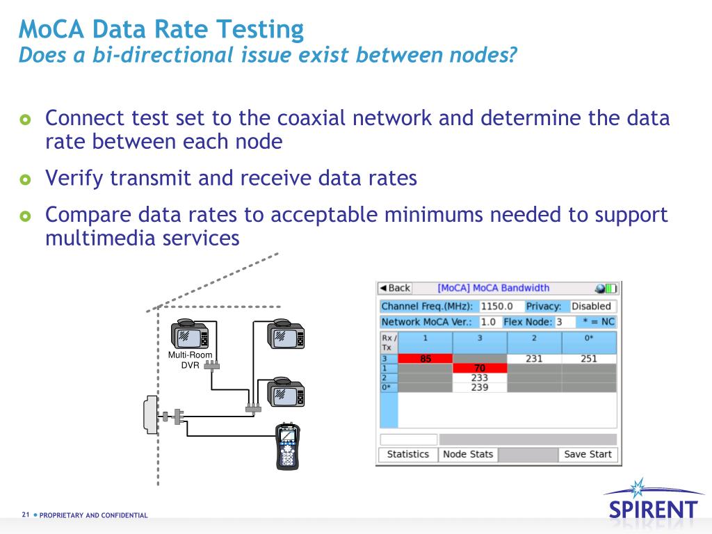

As shown, you can use only the Main Splitter or Splitter 1. RG6 is preferred and is what MOCA 2 was designed for.Ī sketch, as requested earlier, can help us figure out the issue and offer suggestions. MoCA setup diagram: This typical MoCA setup adds two wired computers or any wired devices to the network using a coax cable. If the in wall cabling is RG59, that will also affect the issue. It is the path length and signal loss between each node that determines. That is why this specific drop may not be able to reach the other modem and sync. If you have a central bi-drectional splitter/amp there may be too many connections and cable distance betwenn the two moca nodes for the MOCA modem amp to overcome. Look for Kaufman's posts as he has more engineering data there. Typical budget on a moca modem as about 40 dB if i remember correctly. Your second 'proposed' diagram looks fine (with one adjustment), assuming that the MoCA adapters you choose include a RF pass-through port if not, you'd need to use a MoCA 2.x-compatible splitter at the modem location to get both the modem and MoCA adapter connected to the coax. The combination comes into play for making sync. If there is any damage to a cable within the wall or elsewhere, the signal to noise ratio can be reduced. Per my diagram provided, I have two possible questions: (modem does not have MoCA. If ALL of the splitters in the cable plant are not designed and rated for MOCA 2 specifically, the loss may be too high. Connect the one MoCA adapter to a coax jack in your home and. Typical 2-way splitters introduce about 3.5 dB of loss. It is a home networking technology that makes your WiFi better with a reliable, low latency, and ultra-high-speed connection. It can be much higher with a splitter - either balanced or unbalanced types. The diagram below shows a typical wiring that will work for MoCA. MoCA setup: The devil in the details The coax wiring varies from home to home.
MOCA NETWORK DIAGRAM INSTALL
It uses DLNA to talk with the tv, so any recent tv should work.Each connection on coax introduces about 3dB of signal loss. Making sure your coax wires are intact and connected is the first step in building a MoCA-based network that’s a given. For the cable modem/router that has upper frequency 1218MHz, you need to install two PoE filters. I do both as i had too much loss on one run. Or you could use something like a HD Homerun box and connect to your TVs across ethernet. Actiontec MoCA 2.5 Network Adapter ECB6250 User Guide This Quick Start Guide will walk you through the easy steps to connect your MoCA Network Adapter.
MOCA NETWORK DIAGRAM MANUAL
If this is an indoor antenna, the best spot may be elsewhere in the room. hitron HT-EM4 MoCA 2.5 Network Adapter User Manual Contents hide 1 Getting Started 1.1 Introduction 1.2 Package Contents 1.3 Requirements 1.4 Key Features 2 Connecting the Adapters 2. MoCA uses the existing coaxial wiring already in your home, so it’s easy No need to drill holes or run wires. You might need a higher gain, directional, not omnidirectional, antenna. It is a home networking technology that makes your WiFi better with a reliable, low latency, and ultra-high-speed connection. Is the antenna outside with at least 1.5 meters of air around it or is this an indoor antenna ? You may need to correct the aim of the antenna by a few degrees to improve the signal level, tilt it slightly up, or relocate it to a higher spot with a clear line of sight to the transmission tower. Any unused ports should capped if you cannot replace the splitter with one with the exact number of ports needed. 3 Connect the second adapter into the device you want to use. You can help the losses by replacing any splitters with lower loss versions and minimizing the number. Need help setting up MoCA with Xfinity : r/HomeNetworking. If you have to replace the amp, you will need a low noise version otherwise the noise floor goes up as well. Don’t use push on connectors, use screw on type and make sure they are tight. Make sure there are no shield braid wires contacting the central conductor, the central conductor is proper length from inside the connector with a little bit of the core insulator extending inside. I would start by looking at the coax terminations to the wall plates on each end. If you are having to scan multiple times, that means the signal level is marginal.


 0 kommentar(er)
